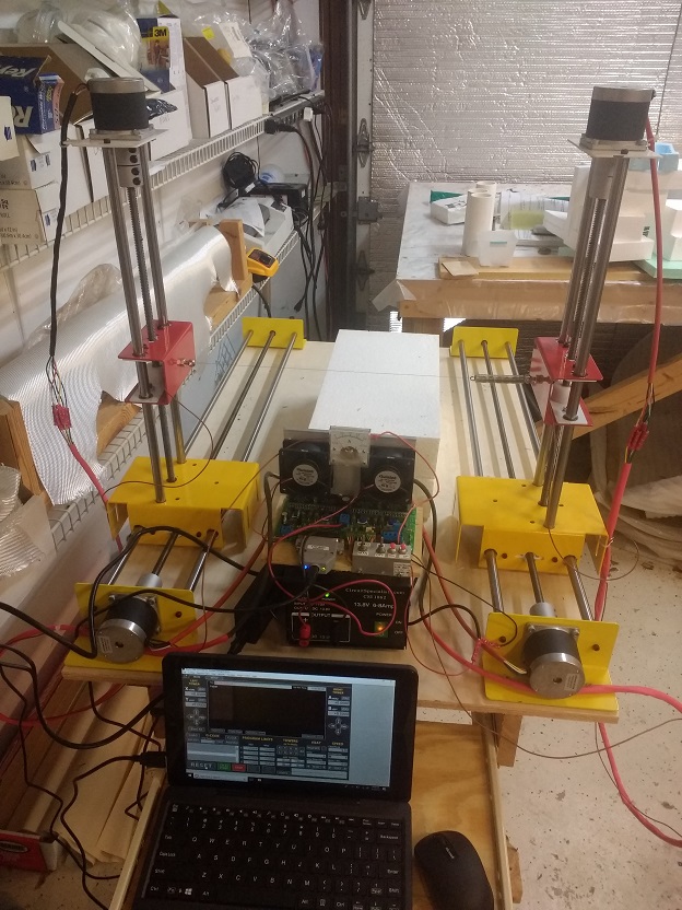
This CNC foam cutter was built from a kit by https://rcfoamcutter.com. It basically consists of two carriages for the horizontal translations and two towers for the vertical translations. I’ve built two prior CNC foam cutters (not using this kit), and the main challenges with those DIY designs were uneven sliding friction and wobble. These problems have been mostly solved in this kit by using plastic bearing sleeves for friction reduction and two linear shafts per axis to reduce wobble. However, it became clear to me later that the wobble is primarily due to lack of straightness in the acme lead screws. Any small bends in the screws will producing a rocking motion of the carriages, which will show up as ripples in the foam edges.
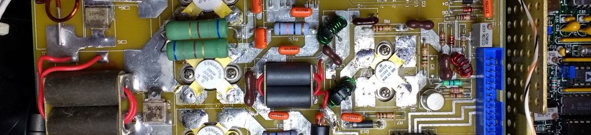
The stepper motors are 6-wire NEMA 23 motors with 2A drive current. The driver board was built from a kit by Hobbycnc (Model #4AUPCWHC). This board includes PWM control of the cutting wire temperature . Unfortunately it appears that they don’t make this board any more.
The control signals are sent via a parallel port connector. The motors need a hefty power supply (up to 8A max), and the hot wire (30-gauge NiCr) also needs a separate power supply.
Most computers nowadays do not come with a parallel port. Although there are USB-to-Parallel converters, they will not work for CNC control because it is impossible to deliver accurate timing signals through the USB port. The solution is to get the UC100 CNC motion controller. It looks like an ordinary USB-to-parallel converter, but it is not. It has an embedded controller to produce the precise signals required for CNC motion control. This allows any laptop with a USB port to be used to drive the CNC. The UC100 is best used with the Mach3 software, which is one of the most widely used CNC software. However, it is a generic CNC software, so some customization (known as “screens”) is necessary. The screens for foam cutting setups can be found in many online forums. I bought mine through Ebay from http://www.foamwings.ru/f-scr_eng.php.
The input commands for the Mach3 software are written in G-codes. These are ascii commands that tell the motors how far to move, and how fast. Some drawing packages such as Inkscape allow saving the vectors as G-codes, but none of them work straight out of the box because the foam cutter drives two pairs of axes – two left axes (X & Y) and two right axes (A & B). Most conventional CNC systems use a single pair of X & Y axes with a Z axis for the height of the cutting tool. There are several software specifically made for foam cutting that can produce four axes G-codes (such as devFoam, Foamworks, Jedicut). However, G-codes for simple non-tapered designs can be easily created from Inkscape, or even from an Excel spreadsheet. The codes can be viewed using a variety of software, such as Camotics.
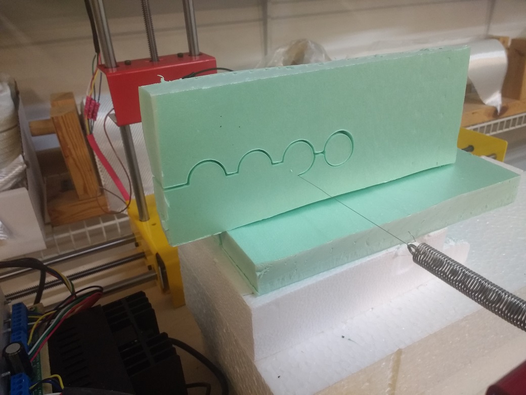
The moving hot wire melts the foam by convective and radiative heat transfer. Therefore, the width of the cut will be larger than the wire diameter. This is known as Kerf, and must be compensated in the design. Kerf is a function of wire diameter, wire temperature, cutting speed and foam type. The best way to determine wire temperature is by using an ammeter to measure the current through the wire. For a given foam type and foam thickness, the temperature is directly related to the current. Low density foam will cut easily and will produce a larger kerf. Slower cut speed will result in a larger kerf. Therefore, the optimum cut speed and temperature has to be determined for each foam type. The width of the foam also matters. A wider foam will draw more heat away the wire, and will require a higher current to maintain the same temperature.
A short tutorial on creating G-codes using Inkscape
This example uses characters, but the same procedure can be used to create cuts from line drawings as well.
- Using inkscape, write the text. A thicker font will be better to give the foam more meat.

- The letters have to be connected, otherwise they will not stay together after the cut. In this example we can place thin rectangles (bars) between the letters to connect them.

- Then switch to outline view. This will show the connecting rectangles as outlines, but the fonts will stay solid. This is because the fonts are lines, not shapes.

- The next step is to convert the letters to shapes, and also combine the letters with the rectangles to create a single structure. This is done by the Union function. Select everything and then click Union. This will produce an outline of the entire object.

- We also need to make access points for the internal holes in the letters O and A. Place small rectangles to make these access cuts.

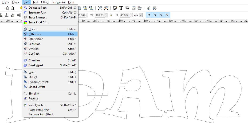
- Unlike the connecting rectangles, these rectangles need to be subtracted from the main object. Select one rectangle, then the main object (with shift-select), and click Difference. Then repeat for the next rectangle.
- There is still one more thing to do. The entry point for the wire has to be defined. By default, the wire will enter from the topmost point in the design, which right now is the top of the letter “A”. I want the wire to enter from the top left corner of the letter “F”. To make this happen, draw a very thin rectangle above F to make it the highest point in the structure. Then combine it with the trace using Union. If this rectangle is very skinny, it won’t show up in actual final cut.

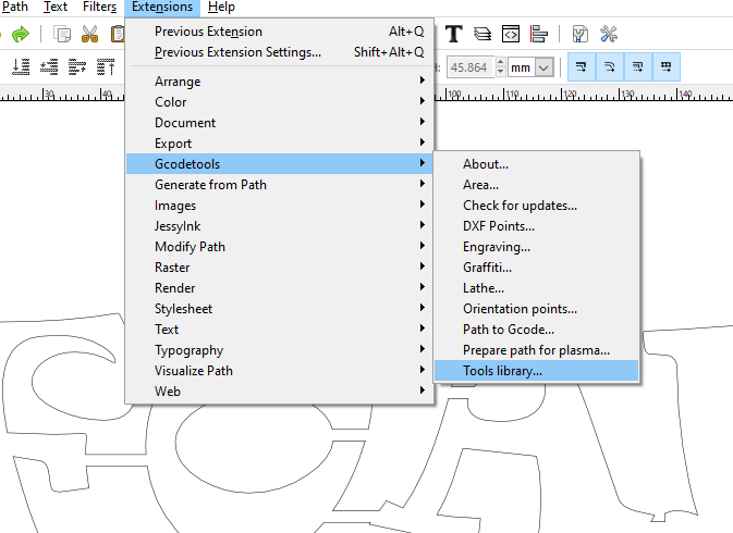
- Next, select Tools library under the Gcodetools extension. Select the default tool and click Apply.
- This will create a table of parameters for the Gcode generation. We don’t need to modify anything here because none of the settings are relevant for a four-axis foam cutter. We will have to manually edit the gcode file afterwards.
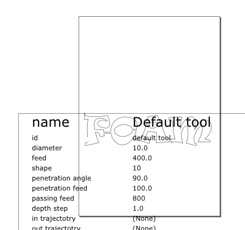
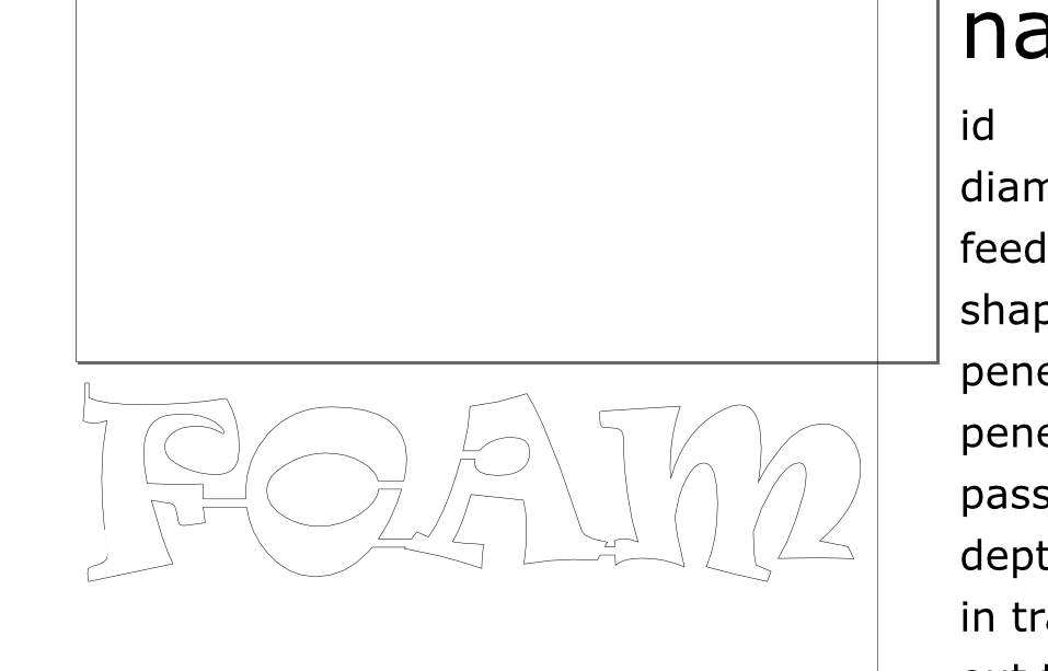
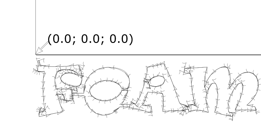
- Move the parameter box out of the way. The (0,0) point is on the lower left corner of the page. I typically like the cut to start from the top left of the shape, so I move the shape below the bottom left corner of the origin as shown below.
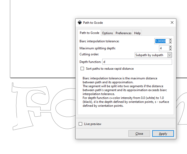
- Under the Gcodetools menu, select Path to Gcode. Accept all the default values except the directory where you want the file to be written, and the file extension (change the .ngc to .gcode). Remain on the Path to Gcode tab and select Apply.
- After the Gcode is created, the trace will change to include small arrows to show the direction of the cutting tool along the trace. The file will have the extention .gcode
- The file will have to be edited with a text editor and modified to match the foam cutter requirements. I usually delete all the preamble and add the following lines:
G17    ( PLANE SELECTION = XY )
G21    ( UNITS = MM )
G90    ( DISTANCE MODE = ABSOLUTE )
M3     ( HOT WIRE = ON )
S50    ( HOT WIRE POWER = 50% )
G4 P5  ( DWELL TIME = 5 SEC )
F400   ( CUTTING SPEED = 400MM/MIN)
- The main section will begin with G00 (rapid movement) in the Z axis to feed the cutter into the work piece, and then another G00 along XY to the first point on the trace. I delete all Z axis movements, and replace the G00 with G01 for a slower translation.
- The main section of the cut trace contains the X, Y and Z axes for linear translations. The two additional I and J fields for curves. On the foam cutter, we have two towers with X, Y, A and B, but we are assuming that A and B slaved to the X and Y. The Z axis is not relevant in this case.
G01 X1.232711 Y-4.768690
G01 X1.232711 Y-7.792300 Z-0.125000 F400.000000
G01 X0.786227 Y-13.993470 Z-0.125000
G03 X1.843255 Y-14.379883 Z-0.125000 I1.879872 J3.503417
G03 X3.365914 Y-14.539170 Z-0.125000 I1.522659 J7.198067
G03 X4.855470 Y-14.401778 Z-0.125000 I-0.000000 J8.143328
- The end of the file must contain the following lines:
G01 X0.0000 Y0.0000
M5    ( TURN OFF WIRE HEAT)
M2    ( END OF FILE )
- Here is the actual file.
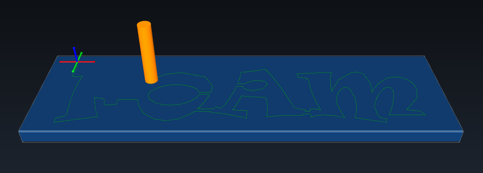
- Open the gcode file using CAMotics. This will show an animation of the cutting process.
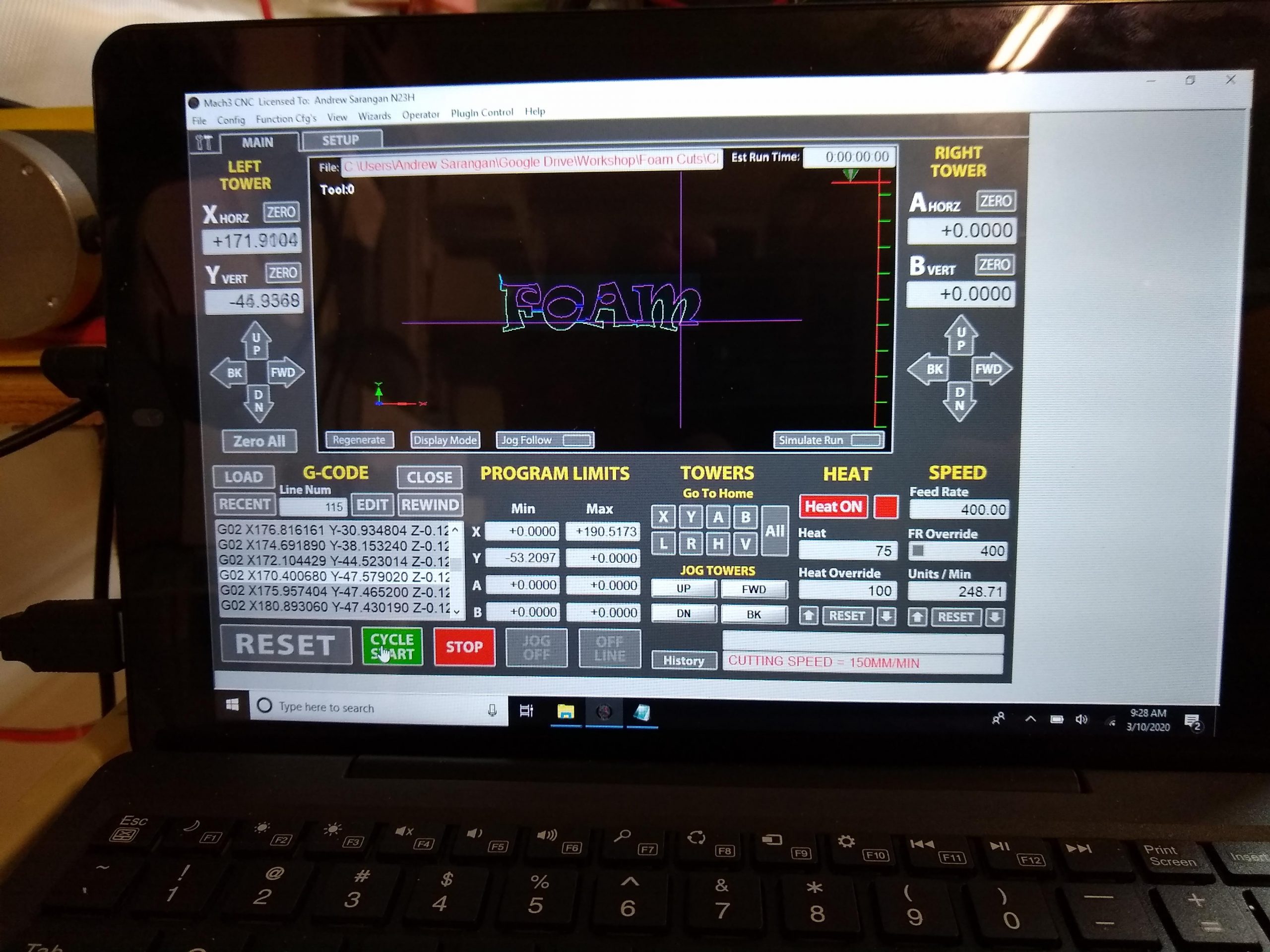
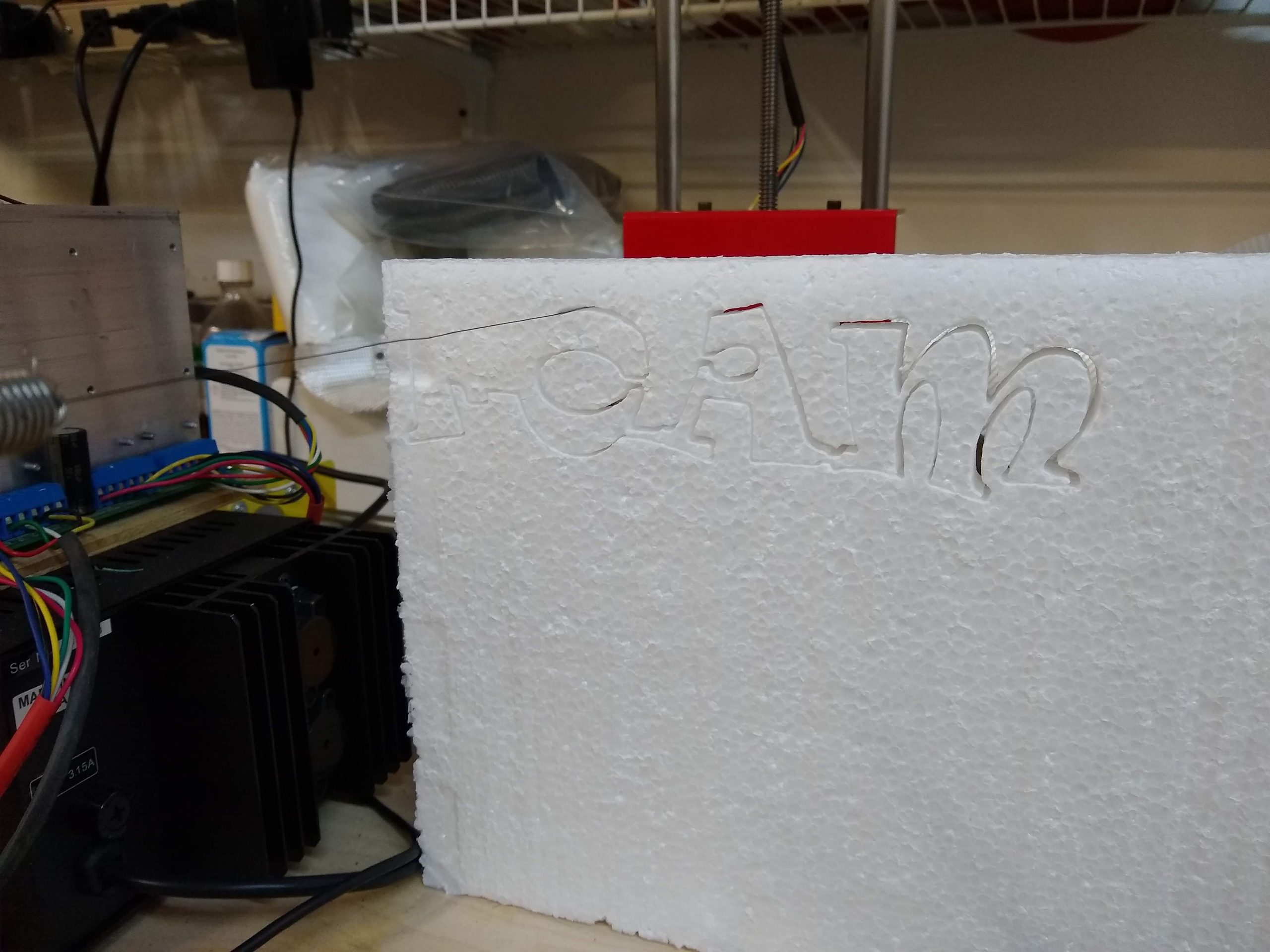
- Load this file into the Mach3 software and execute the cut.

Leave a Reply