Attiny 45/85 microcontrollers are very popular among hobbyists because they are cheap (about $1 each) and can be programmed to do many simple functions. But one thing lacking in these microcontrollers is an integrated USB interface. Many larger microcontrollers come with USB interfaces, but they can be an overkill for many small jobs. One way to get around this problem is by using the V-USB library. This library can be compiled with your regular code to allow chips like Attiny 45 to communicate via USB. However, since it is a software solution to a hardware problem, it comes with some caveats.

Clock
The CPU clock is the most critical aspect of USB signalling. This clock has very tight tolerances, and needs to be one of several specified clock rates (12 MHz, 16 MHz or 16.5 MHz). Using an external crystal oscillator is the best way to ensure accuracy. I don’t know about you, but I don’t have these specific crystals laying around in my component collection. So I would prefer to use the chip’s internal oscillator (known as the RC oscillator). Among the three clock speeds, 16.5 MHz is the most forgiving, making it possible to use the internal RC oscillator. The RC oscillator nominally runs at 8 MHz. By enabling the PLL in the fuse bytes, this can be multiplied 8-fold to 64 MHz. However, the 64 MHz only goes to the peripheral devices. It gets divided by 4, and becomes the CPU clock at a nominal rate of 16 MHz.
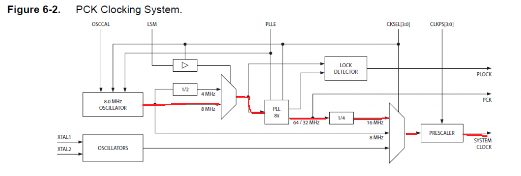
The 8 MHz RC oscillator can be adjusted by writing a value into the OSCCAL register. Increasing numbers increase the clock rate. Therefore, it is possible to tune the oscillator to get 16.5 MHz.
How to measure the CPU clock
The direct method to measure the clock is by sending it to one of the output pins. This can be done by setting the CKOUT fuse bit, which will send the CPU clock to CLKO output (pin #3). This can be measured using a benchtop oscilloscope. Alternatively, it is possible to divide this clock to a slower speed, and then measure it using the Pokitmeter (which is a small tool that runs on the Android phone). It is a lot more convenient (and cheaper) than a benchtop oscilloscope, and you can do it from your office desk. The code below allows the CPU clock to be scaled down by a factor of 2048 for the Attiny 85 chip.

/* Created: 6/20/2020 6:33:18 PM
 * Author : Andrew Sarangan  */

#include <avr/io.h>

/* Fuse bits LOW.CKDIV8 should be unset*/
/* Fuse bits CKSEL(3:0) should be set for 64 MHz, which is 0001*/
/* This fuse is combined with SUT, so the byte is called LOW.SUT_CKSEL */
/* The waveform on 0C1B will be F_CPU/4/256/2. */
/* At 16.5 MHz, the waveform will be 8056.6 Hz */

int main(void)
{
	OSCCAL = 82;  /* This adjusts the RC oscillator frequency */
	DDRB |= (1 << PB4);    /* Use the OC1B function of the PB4 pin */
	TCCR1 |= (1 << CS10) | ( 1 << CS11); /* Divide Timer1 by 4 */
	GTCCR |= (1 << COM1B0); /*Sets the OC1B toggle operation when comparison is successful */
	OCR1B = 0;	/* This is the value to compare with Timer1 */

	while (1){
         ;
	}
}
By flashing this program into the chip, the output on pin #3 can be used to measure the CPU clock. When the CPU clock is 16.5 MHz, the measured pulse rate on pin #4 will be 8056.6 Hz. By trial and error, the value needed to reach 16.5 MHz was found to be OSCCAL = 82.

Voltage Levels
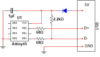
USB power line is 5V, but the D+ and D- lines have to be around 3.3V. This voltage conversion can be done using one of several ways:
- Use a voltage regulator to drop 5V to 3.3V, and run the chip on 3.3V.
- Alternatively, instead of a voltage regulator, a diode (or two) in series can be used to drop the 5V supply down to either 4.3V or 3.6V. Although these are not exactly 3.3V, the USB will still detect the signals correctly.
- We can also run the chip at 5V, and use two 3.3V Zener diodes (small signal diodes, not the regulating type) on the D+ and D- lines to pull the voltage down. This is the least preferred way because the Zener diodes can significantly affect the impedance and the transient response.


Test Results
Clock measurements were made using the Pokitmeter, and whether or not the USB connection worked was determined by connecting to a Windows 10 desktop computer. I did not evaluate the accuracy of the frequency measurement. Your results may vary depending on hardware, operating system, component tolerances and environmental conditions.
| Circuit | Voltage | OSCCAL | Speed | Works? |
|---|---|---|---|---|
| Fig 1 | 3.3V | 81 | 16.440 MHz | No |
| Fig 1 | 3.3V | 82 | 16.517 MHz | Yes |
| Fig 1 | 3.3V | 85 | 16.826 MHz | Yes |
| Fig 1 | 3.3V | 86 | 16.985 MHz | Yes |
| Fig 1 | 3.3V | 87 | 17.148 MHz | No |
| Fig 2 | 4.3V | 81 | 16.328 MHz | No |
| Fig 2 | 4.3V | 82 | 16.516 MHz | Yes |
| Fig 2 | 4.3V | 86 | 16.905 MHz | Yes |
| Fig 2 | 4.3V | 87 | 17.067 MHz | No |
| Fig 3 | 3.55V | 81 | 16.421 MHz | No |
| Fig 3 | 3.55V | 82 | 16.496 MHz | Yes |
| Fig 3 | 3.55V | 86 | 16.960 MHz | Yes |
| Fig 3 | 3.55V | 87 | 17.148 MHz | No |
| Fig 4 | 5V | 83 | 16.611 MHz | No |
Conclusions
The V-USB clock frequency and the voltage levels are surprisingly forgiving. At the 16.5MHz mode, the frequency can be as high as 17MHz (which is almost 3%), but it cannot be lower than 16.5 MHz. The corresponding OSCCAL range was about 82 to 86. The voltages on the data line has to be between 3.3V and 4.3V. Using Zener diodes on the data lines did not work for me, even though I verified that the Zeners were correctly clamping the voltage to 3.5V. Presumably, the switching characteristics of the Zeners were inadequate.
Leave a Reply