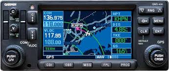
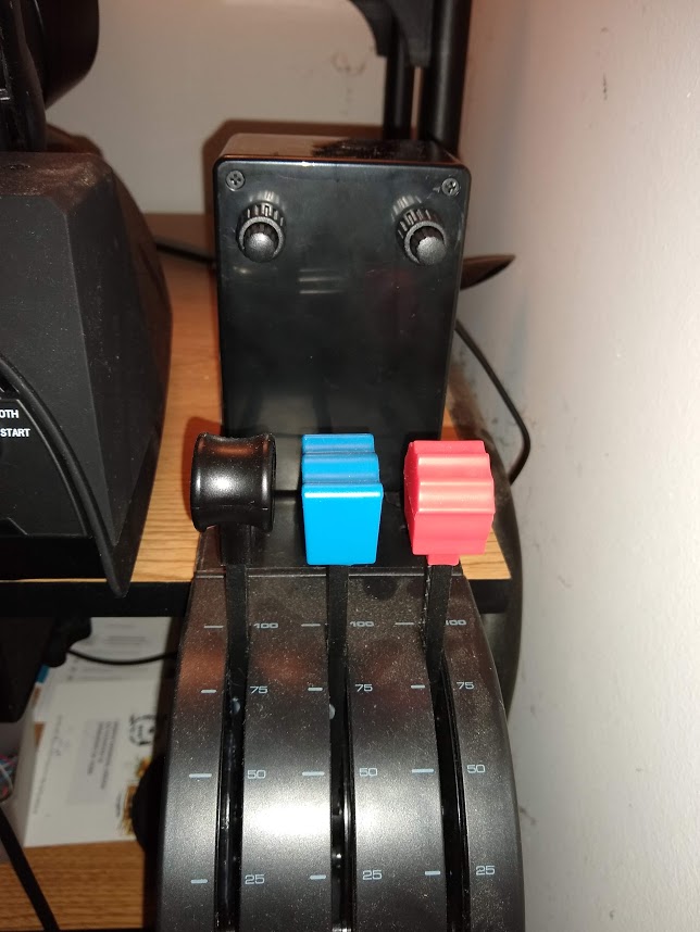
On X-plane, manipulating the Garmin 430/530 keys using the mouse can be cumbersome. Yoke keys can be assigned for these functions, but there are not enough keys on a typical yoke to make this assignment. One solution is to buy a full blown panel such as this one from Realsimgear. But it is expensive. Besides, I really don’t need the display screen because I primarily use Xplane with 3D VR. The best approach for me was to make a simple panel using rotary encoders, and make it communicate with the computer as key presses. This can be built for under $35. So that is what this article is about.
The panel consists of just the two rotary encoders. This was a reasonable choice for me because the other keys on the GNS430 are easy to access using the mouse. Besides, too many physical keys would make it difficult to find them under VR.
The heart of the system consists of two dual-rotary encoders with push button switches, and an Attiny 861A microcontroller. You can get Garmin-style rotary encoders from Propwashsim for $13 each. These encoders are the most expensive part of the whole system.
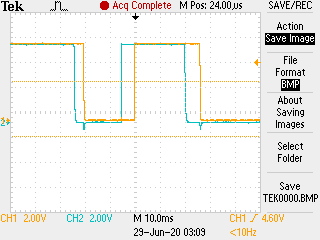
The encoders are not simple potentiometers as one might think. Each click on the knob toggles two SPST switches slightly offset in time from each other. This means, switch #1 will toggle first, followed by switch #2 a few milliseconds later. The sequence will be reversed when the knob is turned in the opposite direction, i.e., switch #2 will toggle followed by switch #1. The microcontroller should sense this timing to determine whether it is a left or right rotation, and then send the appropriate commands through the USB cable.
So, the code has two major parts. The first part is the encoder detection. The second part is the USB communication.
Encoder Detection
The entire code is available on github, but below is the encoder detection part:
tmp = getinput(AorB,pin0);      /* Check Connection 0 */
if (tmp != *state0){            /* If Connection 0 has changed state */
    _delay_ms(delay);           /* Wait for the debounce time */
    tmp = getinput(AorB,pin0);  /* Recheck the Connection 0 state */
    if (*state0 != tmp){        /* If the changed state of Connection 0 is still valid, */
                                /* we can move on to Connection 1 */
        *state0 = tmp;          /* Update the state of Connection 0 */
        tmp = getinput(AorB,pin1); /* Check the state of Connection 1 */
        while (tmp == *state1){  /* Wait for Connection 1 to change state */
            tmp = getinput(AorB,pin1);}
            *state1 = tmp;             /* Update the state of Connection 1 */
The code checks for a change in state (0 or 1) of one of the encoder lines (pin0). A switch debounce delay is used to make sure that it is a persistent change. Then we check the second encoder line (pin1) and wait for that to change. When that change is detected, we can conclude that a one-click turn has occurred. The process is repeated in the reverse direction to detect a turn in the opposite direction.
We have four encoders (each knob has an inner and outer knobs). Additionally, there is also a push-button function on each knob. This makes a total of ten different sensing functions: left/right on each of the four encoders, plus two push button switches. Each one of these functions can be mapped to a key press. In my case, I decided to use A, B, C, D, E and a, b, c, d and e for all ten representations.
USB
Attiny 861A does not have a built-in USB interface. But it is relatively easy to implement this function using the V-USB library. This library mimics the USB hardware function at the software level. The penalty of course is the size of the code (which will inevitably be larger) and the possible reliability issues. But for a simple application like this where the USB device is simply mimicking a keyboard, this should not be a problem. See my previous post on this topic.
Schematic
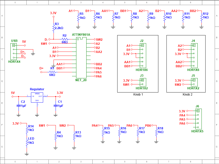
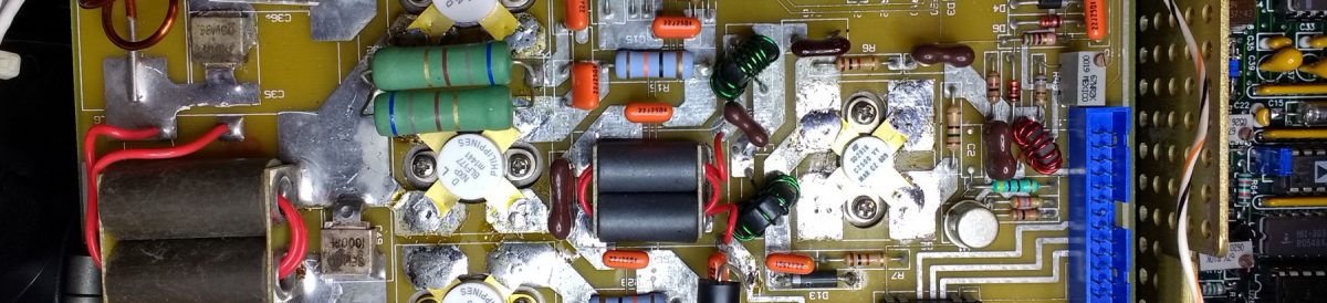
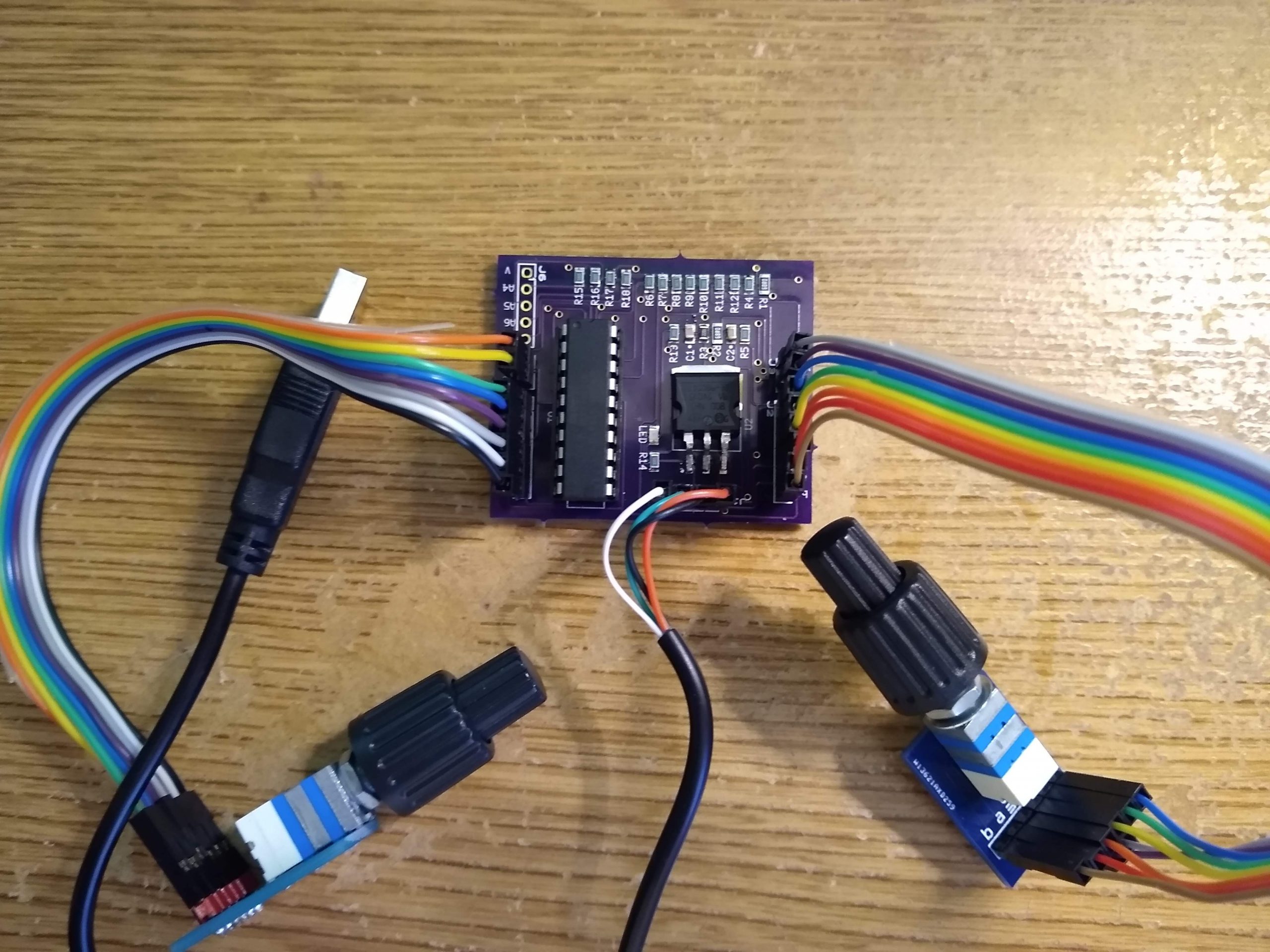
The circuit is relatively simple, though a bit crowded due to the number of wires running between the encoders and the board. I used all surface-mount components except the Attiny861A, which I prefer to have it in a DIP package with an IC socket because it allows me to unplug the chip and flash the program on a separate programming board.
Leave a Reply